Professionals
Central and individual antenna installations for receiving the digital terrestrial TV signal
A well-designed and properly maintained receiving set up is necessary to reproduce the digital signal on the TV sets without problems and as a rule all common home installations are suitable for both digital and analogue signal, so during the digital transition of 2014 it was not necessary to replace the existing equipment.
Main components of the receiving system
TV antenna (aerial)
The TV antenna is the entry point of the DVB-T signal broadcasted by Digea transmitter stations and therefore has a key role in the performance of the whole installation.
The antenna converts the electromagnetic wave (electric field strength measured in dBμV/m) that exists at its installation point (terrace, balcony, indoor space, etc.), into the corresponding electrical signal, which is then passed on to the later stages of the system, until it arrives at the TV set. TV signal antennas are mainly characterized by their gain, measured on logarithmic scale decibels (dBi, dBd or in some cases simply dB for simplification), which practically is the degree of amplification of the received signal, as well as by other secondary characteristics, such as the reception angle or its frequency response. Conventional home TV antennas are directional, i.e. they receive with increased performance in a narrow angle around the direction they are pointed at (typically 30°), while significantly weakening signals that are received from other directions. It is therefore recommended to point the antenna towards the direction of the nearest transmitter station that covers the area and to which there is clear line of sight.
The higher the gain of an antenna, the greater the strength of the received signal, but in some cases it is useful to take into account the secondary characteristics as well, such as the frequency response, depending on the signals transmitted in the area. TV antennas with additional features are now available on the market, such as built-in amplifiers or filters that isolate unwanted interference from other frequency bands (such as broadcasts from mobile communication antennas).
Amplifier
The amplifier is an active (powered) component of the system and in some cases the source of problems in the installation. The amplifier is considered an “active” element as it is fed by electric power, unlike the other parts of the receiving set up (antenna, coaxial cables, and distributors) that do not need electric power to operate and are therefore described as “passive”.
The amplifier can be powered directly by a power supply (central building distribution amplifier) or by using a remote power supply and fed via the transmission line (mast amplifier accompanied by an indoor power supply). Some amplifiers also have a built-in mixer function and can transmit signals of different types (TV, radio, satellite) through the same transmission line.
As indicated by its name, the role of the amplifier is to amplify the receiving signal to compensate for losses caused by the transmission lines, distributors and terminal outlets (TV end plug sockets) of an installation. The main characteristics of an amplifier are its gain, which is expressed in decibels [dB], as well as its maximum output level range, expressed in dBμV.
The build quality of the amplifier also plays an important role, especially when it comes to mast amplifiers that are exposed to outdoor weather conditions. The right choice of amplifier and its reliable operation ensure the uninterrupted signal supply to all TV outlets in the installation whereas, on the contrary, its poor adjustment or malfunction can cause various types of problems in the TV receivers, while in certain conditions (self-oscillation) can even cause interference to nearby buildings.
Due to the advanced technology of the DTT signal, in many cases the use of an amplifier is not required, even though it might had been necessary in an analogue-era installation on the same spot. This is often the case in small receiving set ups (i.e. detached houses), where the digital signal level from the Digea network is sufficient to feed one or two TVs without requiring amplification. In this case, the viewer can avoid unnecessary expenses and labor, so it is recommended first to examine this possibility before deciding to buy and install an amplifier.
Distributors
The distributors are used to split a coaxial transmission line into several, to branch out or feed more devices from the same branch. They are available in different sizes and numbers of outlets (1:2, 1:3, 1:4, 1:6, etc.), depending on the needs of the installation. The higher the number of outlets, the lower the signal level will be at each outlet of the distributor.
Transmission lines [indoor / outdoor coaxial cables]
The signal is transmitted between the various stages of a television installation using coaxial cables with an impedance of 75Ω and with a diameter of 5 to 7 mm, depending on their type. Cables of this type are also used for the in-wall cabling that makes up the distribution network to the TV outlets (sockets) and in this case it is particularly difficult to inspect and replace them if damaged.
The main feature of coaxial transmission lines is attenuation, which is usually expressed in decibels [dB] per 100 meters of cable length. There are also secondary features, such as their rigidity or their special design for resistance to outdoor conditions (usually black colored cables).
Over time, these cables may wear out and their outer insulating layer may be polymerized, thus allowing moisture to penetrate and alter the electrical characteristics of the cable. For this reason, it is recommended to periodically check the condition of the cables (especially outdoor ones) and replace them if traces of wear are detected. In many instances, the replacement of worn cables is sufficient to solve problems that have occurred, thus avoiding time-consuming investigation procedures and unnecessary costs.
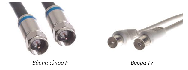
The transmission lines have terminators (connectors) at their ends, usually type F connectors (screw in) or IEC TV connectors (TV), depending on the ports of the connected devices.
Terminal outlets (end plug sockets)
These are the sockets that the signal arrives after going through all the stages of a receiving installation, and of course, the final link which connects the antenna to the TV.
There are two types of sockets: pass-through and terminal. Pass-through sockets require particular consideration, especially in central installations, because they are located at in-between points of the branches and their function is to split the signal strength that reaches them. Part of it is directed to the receiver connected to them [TV or decoder], while the rest of it continues on its way to the next socket. This means that if such a socket is damaged and the signal transmission line is interrupted at that point, then none of the subsequent sockets will receive any signal. Their main characteristic is the ratio of the signal coming out of the socket to the connected receiver, in relation to the signal transmitted to the pass-through circuit and is expressed in decibels [dB].
In order to make the right choice of sockets (especially pass-through ones) it is important to draft a detailed end-to-end design of the installation that will take into account the strength of the received signal, the existence of an amplifier and its output signal level, the number of sockets, etc. The incorrect dimensioning of the attenuation of the sockets in relation to their number and cabling length is often the reason why TV receivers connected to remote sockets have reception problems, while the signal arriving at the first input of the system is strong.
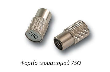
For best results, sockets that are not in use should be terminated using 75Ω termination load plugs. In this way we can avoid signal reflection and formation of standing waves in transmission lines that could, under certain conditions, cause problems in the entire system.
DVB-T signal quality measurements
Measurement equipment
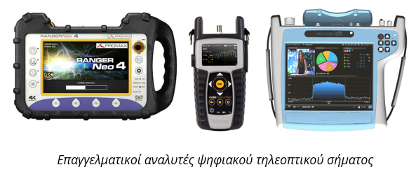
In order to install or troubleshoot a terrestrial television reception installation, either in a residential or a commercial building (e.g. a hotel), a digital terrestrial TV signal analyzer is required.
There are many available options for this type of specialized device, coming from different manufacturers. These typically have many more features than a simple field strength meter and can be customized with a wide range of options and features.
These devices usually can decode and display the actual video stream of the selected service, a feature that comes in handy when multiple signals are received and need to be identified.
Where to measure?
DVB-T signal quality measurements can be carried out at every individual stage in a terrestrial receiving installation, provided that the technician has all the necessary equipment available (analyzer, adaptors, patch cables etc.). On the viewer’s side, a possible problem in the installation is usually noticed at the end of the path, i.e. the socket of the TV set, so that can be a starting point in order to confirm the existence of the problem, but not always what could be the cause of it.
The first step in troubleshooting a reported problem should always be a direct measurement of the signal strength and quality parameters at the reception point, usually the rooftop antenna. Ideally, the antenna itself should not be used, as the goal of this initial measurement is to establish a reference of the available signal in the receiving area, directly from the transmitter station. In this way we can rule out any impairments due to malfunctions within the installation and assess the general signal strength and quality in this specific point.
By comparing this measurement with the one at the TV set, it can be clear whether there is a fault in the installation or if the signal strength is too low in the first place.
In order to carry out this initial rooftop measurement, the technician should use a high quality directive antenna with known characteristics (gain vs frequency, antenna factor, etc) in order to be able to process the measurements taken with it.
This is especially important when reporting possible transmission problems to the network operators, as without those data the measures cannot be reproduced or confirmed.
Following this initial estimation of the available signal at the reception point, the technician can then proceed step-by-step in every following stage (antenna, amplifier, splitter, etc) until the component that causes the problem is found. After that, it should be simple enough to design and implement a suitable solution.
DVB-T signal parameters transmitted by Digea
Video Compression MPEG-4 (AVC/H.264)
Modulation Schemes QPSK, 16-QAM, 64-QAM
Coding Rate 1/2, 2/3, 3/4, 5/6, 7/8
Guard Interval 1/4, 1/8, 1/16, 1/32
OFDM Mode 8K
Channel Bandwidth 8 MHz
Spectrum view
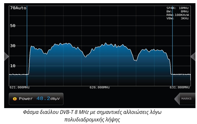
The DVB-T digital terrestrial television signal is composed of a large number of individual carriers closely arranged in an 8 MHz channel. With the appropriate measuring instrument, a technician can view the spectrum content of a digital TV channel at the measuring point, which should ideally be similar to this:
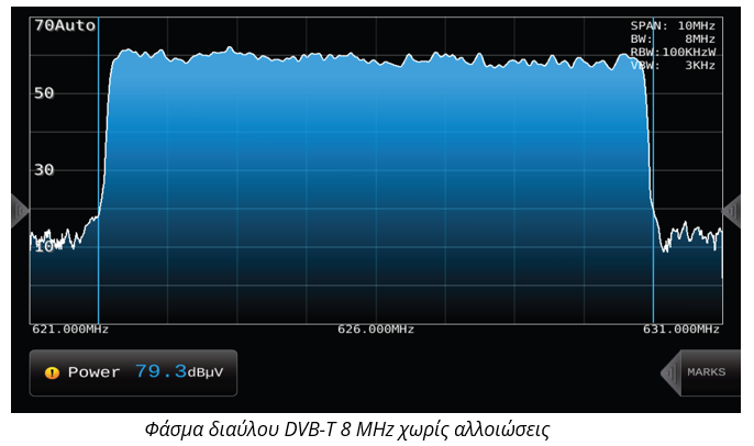
In practice of course, the measured signal at the individual points of a receiving set up rarely has this ideal form, especially if the measurements take place in an installation that is under examination for a possible issue. Depending on the distortions in the measured waveform, the nature of the problem as well as the stage that causes it may be evident.
Field Strength
The field strength of a digital terrestrial TV signal at a given receiving point is expressed in dBμV/m (comparison on a logarithmic scale of the field strength with respect to 1 microvolt per meter). In practice, however, measuring devices (field strength meters or spectrum analyzers) measure either voltage (dBμV) or power (dBm) at their input. To convert these values to the equivalent field strength (dBμV/m) it is necessary to know other parameters, such as the Antenna Factor of the receiving antenna and the cable loss. It is not necessary to use the field strength when performing the measurements, as the values for voltage (dBμV) or power (dBm) suffice to inspect and diagnose the fault in an installation. In any case however, care should be taken to avoid confusion between them, in particular between dBμV and dBμV/m.
The minimum required field strength (or equivalent values) for receiving and demodulating the digital TV signal, depends on the broadcasting parameters (i.e. 16-QAM, 64-QAM, etc.), as well as, to a lesser extent, on the sensitivity of the TV receiver.
Signal-to-Noise Ratio (SNR)
Signal-to-Noise Ratio is the most generic quality measurement of a signal. The result is expressed in decibels [dB] and is the ratio of the level of the desired TV signal to the level of background noise (including the other undesirable signals received, marked as “interference”). Higher SNR values indicate better signal reception.
In digital signals, the SNR measurement gives an overview of the quality of the reception, but often it cannot detect other parameters that affect the end result, such as phase or synchronization problems.
Modulation Error Ratio (MER)
The MER shows the deviation of the digital modulation of the received signal from the ideal modulation scheme. MER, like SNR, is expressed in decibels [dB] and higher values indicate better signal reception. A 64-QAM digital signal for example consists of 64 points [targets] within an 8×8 square grid.
The ideal presence of the 64 symbols emitted is to be right in the center of the squares like a small dot, but in reality the signals received form small “clouds” in each square around its center. Higher MER means smaller and more concentrated “clouds”, looking more like a dot in the center of the square.
The measurement of MER is influenced by almost all parameters that can affect the digital signal, such as the transmitted phase noise, carrier to noise ratio, linear and non-linear distortions, intermodulation, etc.
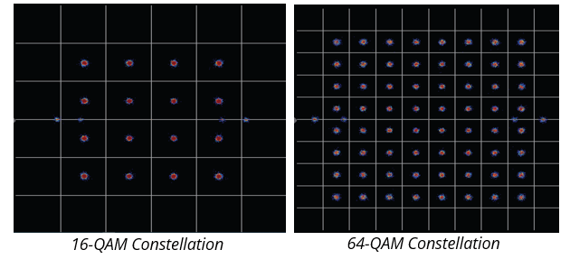
The result of all of the above is that we can never have perfect dots in digital signal analysis. If these distortions are large-scale, some dots are then located outside their “square”, thus they are interpreted as incorrect information.
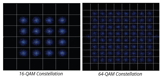
Obviously, the larger the size of the “square”, the smaller the possibility of error, thus the signal is more resistant to distortion, but on the other side, in order to do this there are fewer “squares” so the specific configuration scheme can convey less information (bitrate).
Bit Error Rate - BER
The Bit Error Rate is the measurement of the ratio of incorrectly decoded bits to the total bits received. In other words, it is the number of errors that the digital information has suffered by the time it arrives at the receiving point, in relation to the starting point, i.e. the Digea transmitter station. As the DVB-T signal has more than one layer of encoding, there are many values of BER, each measured at a specific stage of the decoder. Depending on the instrument used, these may have different names (CBER, VBER etc.). The BER measurement in the last stage of decoding (usually named VBER) is the closest indication to the image that the television viewer will see, as a large BER value at that point will inevitably lead to freezes or pixels on the TV screen.
However, in terms of problems identification, it does not offer any particular advantage over SNR or MER measurements and is normally used in combination with them.
Signal Echoes
One of the most remarkable features DVB-T is the ability of the receivers to identify two or more identical signals that are received in one location and treat them as useful contributions instead of interference.
Apart from the obvious advantage in frequency usage, this feature also significantly improves the quality of the reception, as it makes the DTT signal impervious to reflections from nearby obstacles (such as buildings, hills, moving vehicles, etc.). As long as there is a strong “main” signal received, the reception quality will remain steady even in less than perfect conditions. In contrast, an analog TV signal with a secondary reflection from a nearby building would have a “ghost” image appear faintly on the TV screen.
The viewer should normally not be concerned with the SFN reception parameters, as the network operators make sure that the SFN signals arrive synchronized at the service areas. There is however a single specific scenario in which the orientation of the receiving antenna could possibly cause problems in an SFN scenario: when 2 SFN signals of equal strength are received.
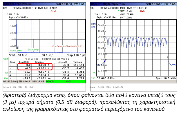
In this case, the 2 signals arrive with different phases and can effectively “cancel” each other, causing problems to the quality of the reception, even though the signal strength remains high. This situation can be identified by using the echo time of arrival mode of a DVB-T analyzer and checking the relative signal strength of the received echo. The effect should also be evident in the spectrum view of the signal that will exhibit a characteristic “sawtooth” pattern: